
Computer networking is a complex world of many protocols and technologies. To help understand networking concepts, we typically reference a network model. This helps to separate out the technologies into easy to digest components.
There are 2 different models often referred to when discussing computer networking
- The TCP/IP model
- The ISO OSI model
TCP/IP model
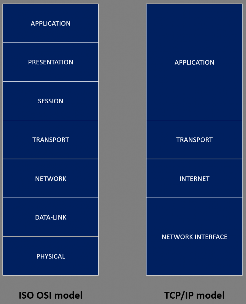
The TCP/IP networking model is a four-layer model that is used for communication over the Internet and most modern networks. It stands for Transmission Control Protocol/Internet Protocol, and it is a suite of protocols that define how data is transmitted between devices on a network. The four layers of the TCP/IP model are:
- Application layer: This layer is responsible for managing application-level protocols that enable programs to communicate with each other. It includes protocols such as HTTP, FTP, SMTP, and DNS.
- Transport layer: This layer is responsible for providing reliable data transmission services to the application layer. It includes protocols such as TCP and UDP.
- Internet layer: This layer is responsible for routing data packets between networks. It includes the Internet Protocol (IP), which provides addressing and routing services.
- Network interface layer: This layer is responsible for transmitting data packets between devices on the same network. It includes protocols such as Ethernet, Wi-Fi, and Bluetooth.
The TCP/IP model is a layered model, which means that each layer is responsible for a specific set of functions, and it interacts with the layers above and below it in a hierarchical manner. This allows devices on different networks to communicate with each other by exchanging data packets that are transmitted over the Internet using the TCP/IP protocol suite.
The OSI /ISO model
The ISO OSI (Open Systems Interconnection) model is a seven-layer model that is used for communication over networks. It was developed by the International Organization for Standardization (ISO) in the late 1970’s to facilitate communication between different computer systems, regardless of their underlying hardware, software, or operating systems.
The ISO OSI model breaks networking technologies into 7 discrete layers. This is very useful when learning about networking concepts as it allows the various technologies to be discussed in more detail than that of the TCP/IP model.
The seven layers of the ISO OSI model are:
- Application layer: This layer is responsible for managing application-level protocols that enable programs to communicate with each other. It includes protocols such as HTTP, FTP, SMTP, and DNS.
- Presentation layer: This layer is responsible for converting data into a format that can be understood by the application layer. It includes protocols such as encryption and compression.
- Session layer: This layer is responsible for managing the establishment, maintenance, and termination of sessions between devices. It includes protocols such as RPC and NetBIOS.
- Transport layer: This layer is responsible for providing reliable data transmission services to the application layer. It includes protocols such as TCP and UDP.
- Network layer: This layer is responsible for routing data packets between networks. It includes protocols such as IP and ICMP.
- Data link layer: This layer is responsible for providing error-free transmission of data frames between devices on the same network. It includes protocols such as Ethernet and Wi-Fi.
- Physical layer: This layer is responsible for transmitting raw bit streams over a physical medium, such as a wire or cable.
As with the TCP/IP model, the ISO OSI model is a layered model, which means that each layer is responsible for a specific set of functions, and it interacts with the layers above and below it in a hierarchical manner. This allows devices on different networks to communicate with each other by exchanging data packets that are transmitted over the network using the ISO OSI protocol suite.
With respect to real-world networking, it is rare to see a system actually split their networking functions into 7 discrete layers. In most practical applications, the networking functions are split into 4 layers which closely follow the model defined by the DoD (Department of Defence).
So, In practice, systems typically follow the 4-layer model, but to understand networking theory, we typically refer to the 7-layer model.
When discussing the 7-layer model, layer 1 is at the bottom (The Physical Layer), and layer 7 is at the top (Application Layer)
It is common to hear people talk about a technology by it’s layer number – for example, people may talk about a layer 3 switch. This is a networking device which usually operates at the Data-Link layer (layer 2), but has the ability to also operate at the network layer (Layer 3)
The models in action
Layer 7 –When an application, such as a browser wants to transmit data, it places its data into the network stack and invokes HTTP (HyperText Transfer Protocol) at layer 7 – The Application layer.
The HTTP adds a set of headers to the data which helps the receiving device know about the application making the HTTP request. This data is then passed down to Layer 6 – The presentation layer
Layer 6 – One of the important functions of the presentation layer is to convert the data into something that can be represented in a binary format for ease of translation to a communications signal, this process is called encoding.
As an example, the letter “A” is encoded as the value of 0041, which can later be converted to the binary of 01000001. This data is now passed down to layer 5 – The session layer.
Layer 5 – When the browser application wants to send its data to a remote device (server), a TCP session has to be established. This session is established by the network stack opening a communications channel (known as a port) from where it will send and receive data. Technologies at the session layer manage these ports, and subsequent communications sessions (known as sockets). Data is then passed down to layer 4 – The Transport layer.
Layer 4 – When sending important data such as web content, or an email, it is imperative that all pieces of data are successfully received. This is one of the many jobs performed by the Transport layer. There are two main protocols which operate at this layer – TCP (Transmission Control Protocol) and UDP (User Datagram Protocol).
TCP is most commonly used in those situations where reliable data transfer is desired. UDP is used in situations where very small packets of data are required to be sent, or if the communication requires speed over reliability. Data is now passed to layer3 – The Network layer.
Layer 3 – Systems involved in communications sessions need to know where to send their data. The protocols at the Network layer provide an addressing scheme (typically IP addressing) that provides this information. This data is now passed to layer 2 – The Data-Link layer.
Layer 2 – The addressing data provided at layer 3 is not used for point-to-point communications between devices (i.e. PC to router, etc.). Typically the data from the higher layers is placed into the payload section of a different protocol – most often Ethernet. This addressing data is managed by the Data-Link layer. The data is now ready for transmission and so is passed to the lowest layer – Layer 1 – The Physical layer.
Layer 1 – At the physical layer, all the above data is converted into a data stream for transmission over the connected transmission medium. This could be copper wires, fibre-optics, or radio waves, etc.
Encapsulation / decapsulation
Encapsulation is the process of adding headers and trailers (footers) to a data packet as it travels through the layers of a network protocol stack. Each layer in the protocol stack adds its own header and trailer, creating a version that includes the original data along with the additional protocol information.
Each layer in the protocol adds its own information to the packet, which is used to help network devices move the packet to its destination and ensure that it is delivered correctly.
When the packet reaches its destination, decapsulation occurs, and the headers and trailers added by each layer of the sending device are removed until the original data is revealed.
Encapsulation is a fundamental concept in networking, as it allows different devices on a network to communicate with each other by transmitting data packets that are formatted in a way that can be understood by the network protocols being used.
Different terminologies are often used to describe the data at different points in the encapsulation process.
The terms datagram, packet, and frame are used to describe different types of data units that are used to transmit information across a network.
- Datagram: A datagram is a self-contained unit of data that is transmitted over a network without any guarantees of delivery or reliability. It is typically used in connectionless network protocols, such as UDP (User Datagram Protocol). A datagram contains a payload of data along with the source and destination addresses, but it does not include any additional information, such as sequencing or error-checking data.
- Packet: A packet is a unit of data that is transmitted over a network and contains additional information that is used to ensure reliable delivery of the data. Packets are typically used in connection-oriented network protocols, such as TCP (Transmission Control Protocol). A packet contains a payload of data, along with additional information such as the source and destination addresses, sequencing data, and error-checking data.
- Frame: A frame is a unit of data that is transmitted over a physical network medium, such as an Ethernet cable or a wireless connection. It includes the packet, along with additional information that is used to transmit the data over the physical medium. This includes information such as the physical addresses of the source and destination devices, and error-checking data such as cyclic redundancy checks (CRCs).