We all have one. It might be a box, an old carrier bag, or even a dedicated drawer – A tangled collection of USB cables that we simply can’t bring ourselves to throw away
“I might need one of these one day” – is the cry heard across the land when told to get rid of them
Why do you need more than one? They’re all the same aren’t they?
Well – no, they aren’t all the same, As I recently discovered to my cost.
Recently I was attempting to move 4.5Tb of media from an internal PC drive to an external drive – I plugged one end of the USB cable into the PC and the other into the portable drive.
The portable drive had a USB-C connector, so I’d bought what I thought was a USB 4 cable and was expecting the data move to take half an hour at most – the reality was that it took nearly 2 full days to move everything across
I was shocked at how slowly it was progressing, so I decided to delve into the USB standards to see if I could figure out what was happening.
Let me state that I’ve been in the IT world for most of my life – I grew up in the golden age of home computing in the 1980’s with Sinclair Spectrums, Commodore 64’s, etc. and have been fortunate to see the evolution of PCs in the workplace – From the old 80286’s through the Pentium era, to the latest Intel core ultra 3 “Panther” CPUs. I’ve used (almost) every version of Microsoft OS from Dos v2 through to Windows 11, and although I no longer use them, have used various MAC OS systems and am a regular Linux user.
I understand most technical standards used in computing (TCP/IP, Ethernet, OSPF, SMTP, LDAP, HTTP, etc.) but apparently the USB standards have completely slipped past me.
The evolution of USB has been varied and complex, so lets take a look at how USB has changed over the years
First of all, we need to understand that the term USB has two perspectives – one which defines the specification (i.e. the speed of the connection, the bandwidth, and the power consumption) and one which defines the type (shape) of connector used.
USB 1.0
USB 1.0 was released in January 1996 and had specific bandwidth speed of 1.5 Mbps, it did not have wide adoption due to timing and power limitations.
USB 1.1
It wasn’t until the release of USB 1.1 in August 1998, which increased bandwidth to 12 Mbps, that USB became popular.
USB 2.0
Released in April 2000, USB 2.0 saw an increase in maximum signal bandwidth speed to 480Mbps and was labelled High Speed as it was 40 times faster than its USB 1.1 predecessor.
USB 2.0 was intended for 3 applications; digital storage, digital imaging, and communications. This was the most widely adopted USB to date.
USB 2.0 also allowed for charging of devices rather than simply transferring data between devices, this completely changed the landscape of the technology as USBs are now being used outside of its initial intended data application.
USB 1.0 – 2.0 connectors
Standard-A
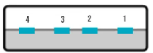
Standard-A connectors have four pins. Pin 1 is +5V, Pins 2 & 3 are Data, and Pin 4 is the ground pin. This is the most common type of USB connector and is typically used for connection to a device such as a PC, or laptop, but are also used without the outer plastic sleeve with USB flash drives. The connectors can be coloured either black or white

Standard-B
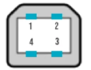
Standard-B connectors also have four pins, Two for power, and two for data. These are commonly used for connecting to devices such as printers. The connectors are typically white
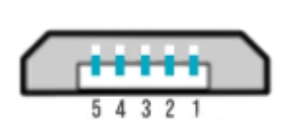
Mini-A & Mini-B
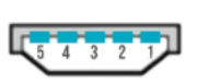

Mini-A & Mini-B connectors have a fifth pin called the ID pin which is typically not connected but is used to determine an On-The-Go (OTG) device. These were commonly used for connecting to mobile phones.
Pin 1 is the +5V power, Pins 2 & 3 are data pins, Pin 4 is the ID pin, and pin 5 is the ground pin.
An OTG device is one which can assume the role of host device as opposed to being a peripheral device
An OTG device with an A plug inserted is called the A-device and is responsible for powering the USB interface when required, and by default assumes the role of host. An OTG device with a B plug inserted is called the B-device and by default assumes the role of peripheral
Micro-A & micro-B
Micro-A & Micro-B connectors superseded the Mini connectors because of their reduced size, to can be fitted to thinner mobile devices

USB 3.0
Released in November 2008, USB 3.0 is also known as Superspeed USB because of its 5Gbit/s data transfer rate
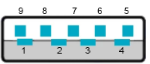
USB 3.0 increased the number of connectors from 4 to 9 to provide full-duplex data transfers at SuperSpeed, making it similar in throughput to that of single-lane PCI Express – Perfect for the quick transfer of data such as photos from a digital camera direct to the PCIe bus in the PC for display on the monitor via the graphics card.
Pin 1 is the +5V, Pins 2 & 3 are data pins, pin 4 is the ground pin – these pins allow for backwards compatibility with USB 2.0 devices. Pins 5 & 6 are the Superspeed data pins for receiving data, pin 7 is the ground, and pins 8 & 9 are the Superspeed data pins for transmitting.
To aid identification, USB 3.0 connectors are coloured dark blue

USB 3.1
In January of 2013 the USB group announced a rebranding of the USB 3.0 specification and stated that USB 3.1 gen1 replaced the existing USB 3.0
USB 3.1 gen2 was released in July 2013, USB 3.1 gen 2 doubled the speed of USB 3.0 gen1 to 10Gbit/s
USB 3.1 connectors are coloured light teal

Some devices offer a Sleep-and-charge capability that allows a device, such as a PC to charge a peripheral (e.g. mobile phone) even when the PC is switched off. These connectors can be identified by the Yellow, orange, or red USB connector.

USB 3.0 – 3.1 connectors
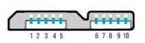
Standard-A
Standard-B
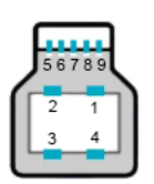
Micro-B
The Superspeed USB 3.0 Micro-B connector was designed so that it was backward compatible with the USB 2.0 Micro-B cables. users with a USB2.0 cable can simply plug the cable into the side with pins 1 to 5
USB-C
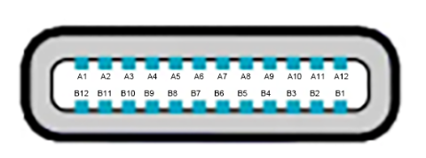
At roughly the same time as the development of USB 3.1 gen2, the USB-C connector was being developed. USB-C is a 24-pin reversible connector (not a protocol) that supersedes all previous USB connectors, which were designated legacy in 2014.
This connector type can be used for other data transfer protocols besides USB, such as Thunderbolt, PCIe, DisplayPort, and HDMI. It is considered extensible, allowing the support of future protocols.
The connector features four power and four ground pins, two data pairs for legacy USB 2.0 high-speed data, four shielded data pairs for Enhanced SuperSpeed data (two transmit and two receive pairs), two Sideband Use (SBU) pins, and two Configuration Channel (CC) pins. These signals are used to determine the orientation of the cable, as well as to carry USB Power Delivery communications.
USB 3.2
On 25 July 2017, a press release from the USB 3.0 Promoter Group detailed an update to the USB Type‑C specification, defining the doubling of bandwidth for existing USB‑C cables.
Under the USB 3.2 specification, released 22 September 2017, existing SuperSpeed certified USB‑C 3.1 gen1 cables can operate at 10 Gbit/s (up from 5 Gbit/s), and SuperSpeed+ certified USB‑C 3.1 gen2 cables can operate at 20 Gbit/s (up from 10 Gbit/s).
The increase in bandwidth was as a result of multi-lane operation over the existing connectors that were intended for flip-flop capabilities of the USB‑C connector
This announcement also renamed the existing USB branding:
- SuperSpeed USB (based on SuperSpeed architecture and protocols):
- USB 3.2 Gen 1×1 – newly marketed as SuperSpeed USB 5Gbps replaces USB 3.1 gen1, which replaced USB 3.0
- SuperSpeedPlus USB (based on SuperSpeedPlus architecture and protocols):
- USB 3.2 Gen 2×1 – newly marketed as SuperSpeed USB 10 Gbps replaces USB 3.1 gen2.
- USB 3.2 Gen 1×2 – new, 10 Gbit/s signalling rate over 2 lanes
- USB 3.2 Gen 2×2 – new, marketed as SuperSpeed USB 20 Gbps, 20 Gbit/s signaling rate over 2 lanes
USB 4
Released in 2019, USB 4 enables multiple devices to dynamically share a single high-speed data link, and defines bit rates of 20 Gbit/s, 40 Gbit/s and 80 Gbit/s
The USB4 standard mandates backward compatibility to USB 3.x and dedicated backward compatibility with USB 2.0
USB 4 V2.0
On 18 October 2022 the USB Promoter Group released the USB4 Version 2.0 specification which added a new transmission speed that allows 80 Gbit/s symmetric connections or asymmetric connections supporting 120 Gbit/s in one direction and 40 Gbit/s in the other
Final thoughts
So, now we can see the evolution of USB hasn’t been exactly simple. A confusing mix of rebranding, and the separate development of the data protocol standard, and the connector types has led to a confusing array of cables, connectors and bandwidth capabilities.
This difference between the USB protocol and the USB-C cable specification was the primary reason why the cable I was using, although a USB-C design, was not transferring data at USB 3.1, or even USB 4.0 rates – it was only transferring at USB 2.0 rates.
So, when buying a new USB cable, I have learned to look at the details of the cable specification
Take the example below – This cable is a USB-C cable
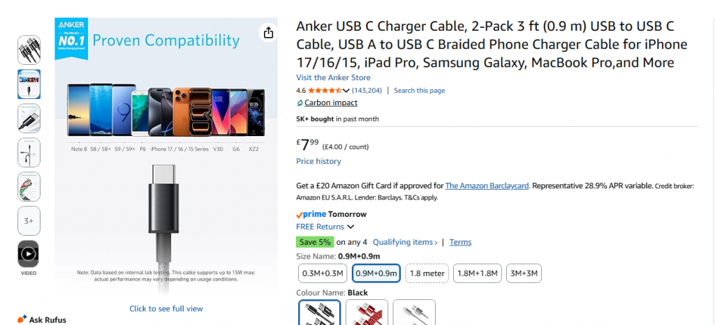
However, when you look at the detailed spec, it states a data transfer rate of 480Mbit/s
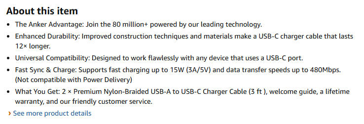
So whilst it is a USB-C, this places the cable in the USB 2.0 range for data speeds
This cable on the other hand, is also a USB-C
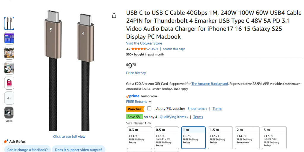
But has a rated speed of 40Gbit/s, making it a USB 4.0 rated cable
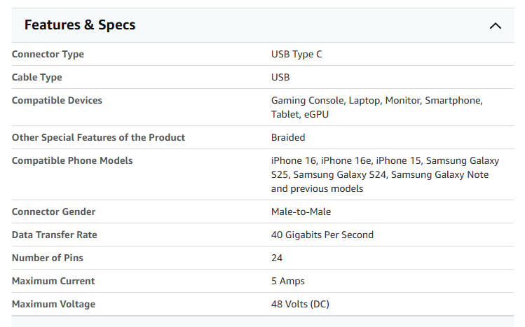
If you look closely at the second cable, There are some giveaway signs of its capabilities – One end has the number 4, whilst the other has a lightning bolt icon.
This is because with the release of USB 4, the standard introduced stricter labelling rules. Cables now show direct speed ratings, such as “USB 40Gbps” for standard USB4, and power indicators, such as “240W” or “PD 3.1”, to confirm high-power charging capability.
The lightning bolt icon signals Thunderbolt compatibility, which layers guaranteed minimum performance specs on top of the USB4 foundation. If there’s no speed label and the design looks basic, you’re almost certainly looking at a USB 2.0 cable, regardless of the connector shape.
Additional to this, USB4 and high-power USB-C cables must also include electronic marker chips, called E-Marker chips, that communicate their capabilities to connected devices.
If you have a Fast-charge 100W USB charging plug, you might find that its useless if your USB-C cable doesn’t have this spec, as the chip tells your device exactly how much power and data the cable can safely handle. This means a properly certified USB4 cable actively introduces itself to your hardware and negotiates the best possible connection, rather than leaving your devices to guess, and typically drop to the lower rating for safety.
Post 72 – 03/03/2026